How to Create Software Architecture Diagrams Using the C4 Model
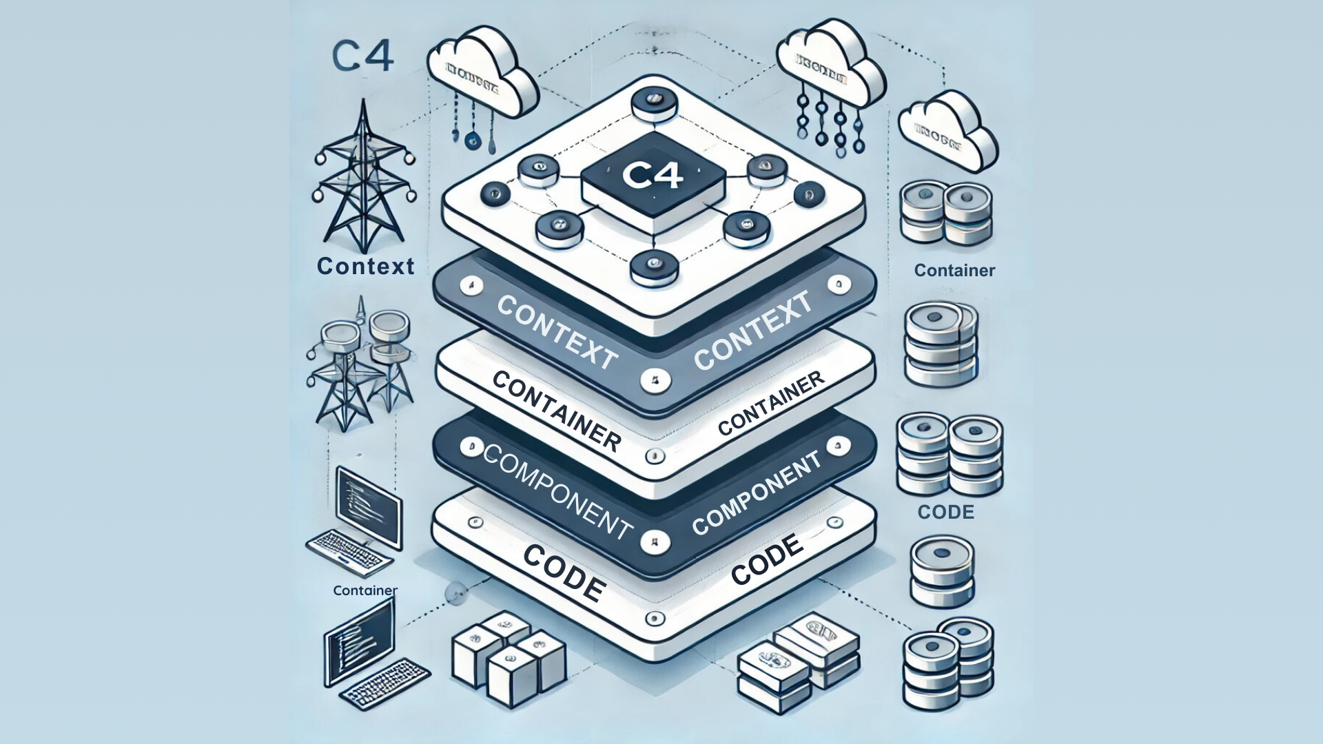
The C4 Model is a simple yet powerful framework for creating clear and structured software architecture diagrams. It helps represent different levels of a software system's architecture through four distinct layers:
1. Context Diagram
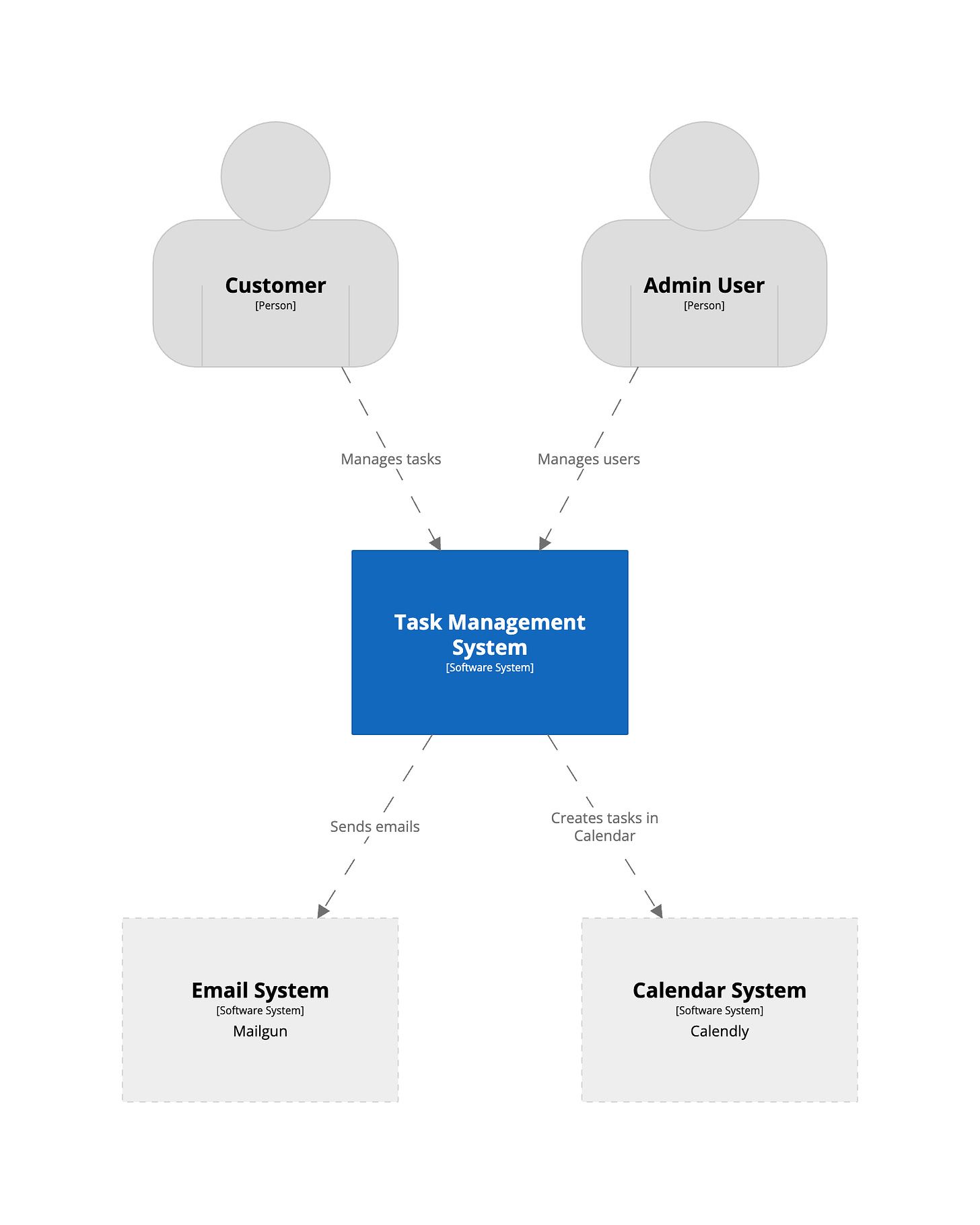
The context diagram provides a high-level view of the system, illustrating how it interacts with external users, systems, and entities. It shows the scope of the system and outlines its boundaries. The goal is to help stakeholders understand the system's environment and external dependencies without going into technical details.
2. Container Diagram
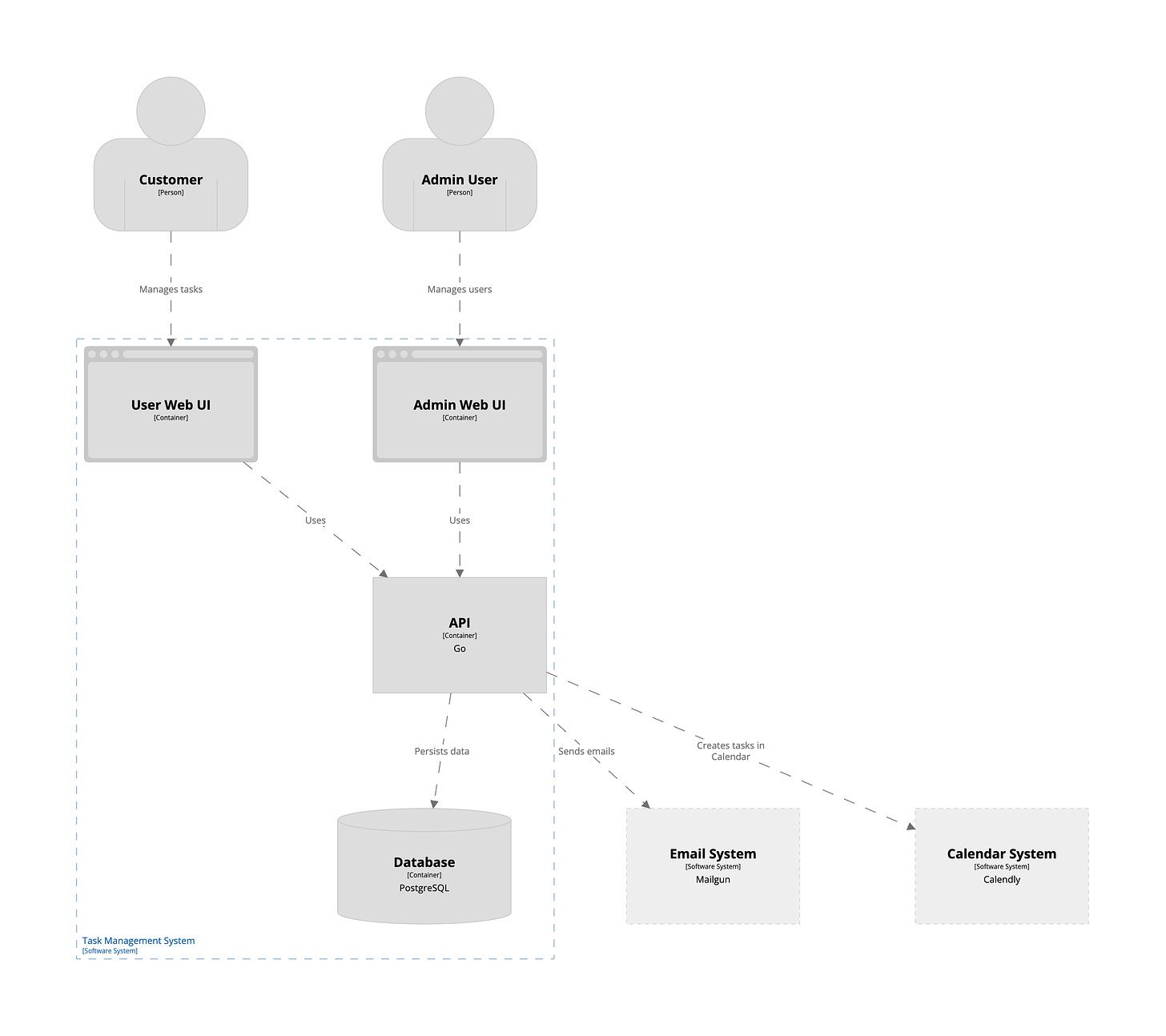
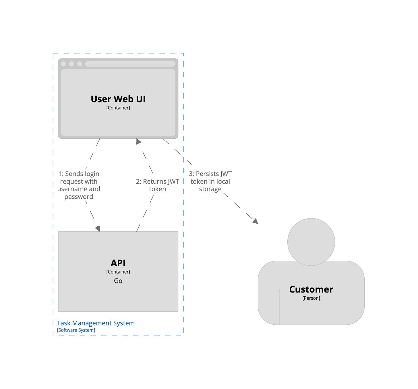
The container diagram zooms in to show the different "containers" (applications, services, or databases) that make up the system. Each container is a runnable software component responsible for executing a specific function, like a web server, mobile app, or database. This layer helps developers understand how the system is organized and how the different containers communicate with one another.
3. Component Diagram
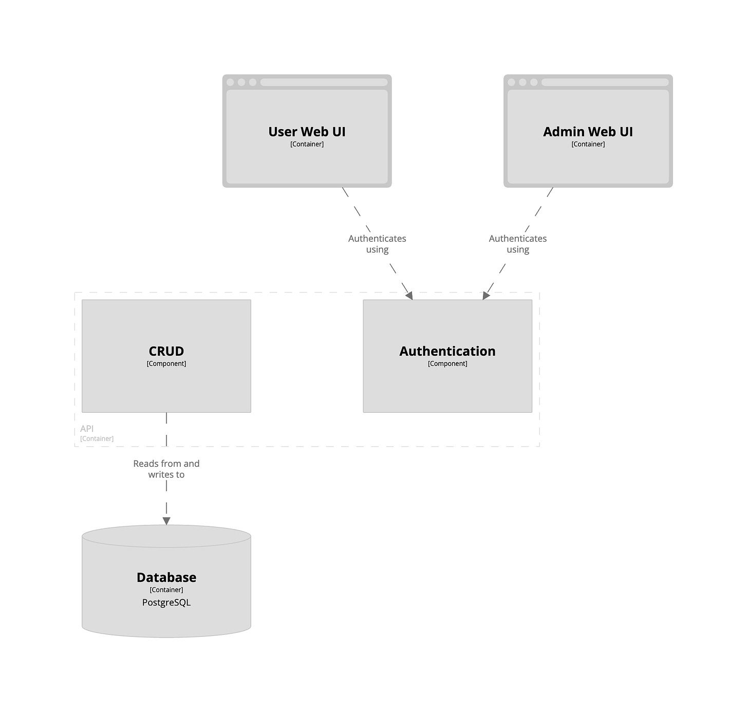
This layer breaks down each container further into components, such as services, classes, or functions, that make up a specific container's functionality. The component diagram helps understand the internal structure of each container, showing how responsibilities are divided and which components interact.
4. Code (Class) Diagram
The final layer dives into the code details, representing class-level diagrams and specific code structures. Although optional, this level is useful for providing detailed documentation of complex code components for those who need an in-depth understanding of the codebase.
Benefits of Using the C4 Model
- Simplification: Helps break down complex systems into manageable levels of detail.
- Communication: Provides a shared understanding of system architecture among teams.
- Scalability: Applicable to both simple and complex systems.
- Clarity: Each level provides a different view, ensuring all stakeholders grasp the architecture at their needed level of detail.
Step-by-Step Guide to Creating C4 Diagrams
- Start with a Context Diagram: Outline the system's external interactions.
- Move to a Container Diagram: Break down the system into containers like applications and databases.
- Detail each container in Component Diagrams: Identify key components and their roles.
- Include Code Diagrams if needed: For detailed documentation of specific code structures.
Tools for C4 Diagram Creation
- PlantUML: Allows you to generate C4 diagrams using simple text-based instructions.
- Structurizr: Designed specifically for creating C4 model diagrams.
- Microsoft Visio: A more traditional tool for creating diagrams that can be adapted for C4.
The C4 Model helps bridge the gap between different stakeholders by providing a visual representation that caters to both technical and non-technical audiences.

